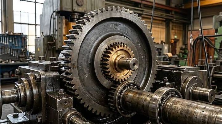
Industrial Gearboxes Guide: Designs, Gear Ratios, Operating Principles and Industrial Uses
An Industrial Gearboxes Guide explains how industrial gearboxes work, the designs they use, how gear ratios affect machine performance, and where these mechanical systems are applied. An industrial gearbox is a device that transfers rotational power from a motor or another driving source to a machine while changing rotational speed and torque.
Context
An Industrial Gearboxes Guide explains how industrial gearboxes work, the designs they use, how gear ratios affect machine performance, and where these mechanical systems are applied. An industrial gearbox is a device that transfers rotational power from a motor or another driving source to a machine while changing rotational speed and torque. Gearboxes have developed alongside mechanical engineering, from early gear-driven machinery to modern precision systems used in automated factories, transport equipment, and heavy industrial plants.
Industrial gearboxes contain interconnected gears supported by shafts, bearings, and a housing. Depending on their design, they can reduce speed, increase output torque, change the direction of rotation, or transfer motion between shafts positioned at different angles. Their configuration depends on the machine's load, operating speed, available space, and working environment.
Understanding Industrial Gearbox Designs
Different gearbox designs are suited to different mechanical requirements. The main differences involve gear arrangement, shaft orientation, load capacity, operating characteristics, and installation space.
Helical gearboxes: Use angled gear teeth that engage gradually. They are commonly used in conveyors, mixers, and manufacturing equipment where smooth power transmission is important.
Spur gearboxes: Use straight teeth positioned parallel to the gear axis. Their relatively simple design makes them suitable for many general mechanical applications.
Bevel gearboxes: Transfer rotation between intersecting shafts, often at a right angle. They appear in machinery requiring a change in the direction of power transmission.
Worm gearboxes: Use a screw-like worm engaging with a worm wheel. They can provide substantial speed reduction in a compact arrangement, although sliding contact can produce additional heat.
Planetary gearboxes: Arrange several planet gears around a central sun gear inside a ring gear. Their compact layout supports applications requiring high torque relative to their size.
Cycloidal gearboxes: Use an eccentric mechanism and cycloidal disc to transmit motion. They are used in some applications requiring compact construction and resistance to shock loading.
Each design has different efficiency, noise, maintenance, and load characteristics. The appropriate configuration depends on the operating requirements rather than the gear type alone.
Importance
Industrial gearboxes are important because many machines cannot operate effectively at the rotational speed produced by their motors. Conveyors may need controlled movement, lifting equipment requires substantial torque, and processing machines often need stable speeds to handle materials consistently. A gearbox helps match the motor's output to these mechanical requirements.
Gearbox performance also affects energy use, equipment reliability, production continuity, and workplace safety. Incorrect selection, inadequate lubrication, misalignment, or excessive loading can contribute to overheating, vibration, premature wear, and unexpected equipment shutdowns.
How Gear Ratios Affect Performance
A gear ratio describes the relationship between the rotational speeds of the input and output shafts. For a simple gear pair, the ratio can be calculated by dividing the number of teeth on the driven gear by the number of teeth on the driving gear.
For example, if a 20-tooth driving gear rotates a 60-tooth driven gear, the ratio is 3:1. In an ideal arrangement, the output shaft rotates at one-third of the input speed while producing approximately three times the input torque, before accounting for mechanical losses.
The relationship can be summarized as follows:
| Gear ratio | General speed effect | General torque effect |
|---|---|---|
| 1:1 | Similar input and output speed | Similar torque before losses |
| 2:1 reduction | Output speed is about half | Output torque is about double |
| 3:1 reduction | Output speed is about one-third | Output torque is about three times |
| 5:1 reduction | Output speed is about one-fifth | Output torque is about five times |
These examples assume a reduction gearbox and ideal mechanical conditions. Actual output torque is lower because of friction and other losses. The direction of rotation and shaft arrangement also depend on the gearbox design.
Operating Principles and Main Components
An industrial gearbox receives mechanical power through an input shaft. The input gear drives one or more connected gears, transferring motion through the internal gear arrangement before power leaves through the output shaft.
Several components support this process:
Gears: Transfer motion and establish the required speed relationship.
Shafts: Carry rotational movement into and out of the gearbox.
Bearings: Support rotating shafts and help control friction and movement.
Housing: Holds the components in alignment and protects them from environmental contamination.
Lubrication system: Reduces friction, limits wear, and helps carry heat away from contacting surfaces.
Seals: Help retain lubricant and limit the entry of dust, moisture, or other contaminants.
Lubrication requirements vary with gear design, speed, load, temperature, and manufacturer specifications. Some gearboxes use oil baths or circulation systems, while others use grease or different arrangements suited to their construction.
Recent Updates
Industrial gearbox development increasingly focuses on energy efficiency, condition monitoring, compact mechanical designs, and integration with automated manufacturing systems. Across 2024–2026, these areas have remained relevant as industrial operators seek to manage energy consumption, reduce unplanned downtime, and understand equipment condition more clearly. Specific capabilities vary by manufacturer and application.
Digital Monitoring and Predictive Maintenance
Some modern gearbox installations use vibration sensors, temperature sensors, oil-condition monitoring, and connected control systems to identify changes in operating behavior. These measurements can help maintenance teams detect possible problems such as bearing wear, lubrication issues, misalignment, or unusual loading.
Predictive maintenance uses condition data to estimate when equipment may require inspection or intervention. It does not eliminate mechanical failures, and sensor readings need to be interpreted in context. Incorrect sensor placement, changing operating loads, or unsuitable alarm thresholds can affect the usefulness of monitoring systems.
Energy Efficiency and Design Improvements
Gearbox manufacturers continue to develop designs intended to reduce mechanical losses, improve thermal performance, and support specific machine requirements. Improvements may involve gear geometry, bearing arrangements, surface treatments, lubricant selection, and manufacturing precision.
Integration with variable-frequency drives is also relevant in industrial installations. These drives adjust motor speed according to operating requirements, while the gearbox establishes the mechanical relationship between motor rotation and machine movement. Their combined performance depends on proper sizing, control settings, and the operating load.
Compact planetary designs and modular gearbox configurations are also used where installation space, torque requirements, and maintenance access influence equipment design. No single configuration suits every industrial application.
Laws or Policies
Industrial gearboxes are affected by workplace safety requirements, machinery regulations, electrical installation rules, environmental obligations, and applicable engineering standards. The precise requirements depend on the gearbox's intended use, the machine in which it is installed, and the country where the equipment operates.
Industrial Equipment Requirements in India
In India, industrial gearbox installations may fall under broader workplace safety and machinery requirements. Applicable central and state legislation, factory safety rules, electrical safety provisions, and environmental requirements may be relevant depending on the facility and activity.
The Occupational Safety, Health and Working Conditions Code, 2020, forms part of India's occupational safety framework, with practical obligations depending on its implementation and applicable rules. Machinery operators and facility managers must determine which provisions are in force and apply to their workplace.
Engineering Standards and Workplace Safety
International standards can help engineers evaluate gearbox dimensions, testing methods, terminology, and performance. ISO standards address various aspects of gear design and engineering, while IEC standards may be relevant to associated electrical motors and equipment. The specific standard depends on the application and equipment specification.
Workplace safety measures may include guarding rotating shafts, preventing accidental machine startup during maintenance, controlling access to hazardous moving parts, and following appropriate inspection procedures. Equipment used in potentially explosive atmospheres may require additional protection and conformity assessment.
Gearbox selection and installation should account for the manufacturer's rated torque, permitted input speed, lubrication requirements, mounting position, and thermal limits. Compliance should be assessed against the applicable rules and standards rather than assumed from a product description.
Tools and Resources
Several technical resources help engineers, maintenance personnel, students, and equipment operators understand industrial gearbox specifications and operating conditions.
Gear Ratio and Torque Calculators
Online gear ratio calculators can estimate the relationship between input speed, output speed, and gear tooth counts. Torque calculations can help explain how a reduction ratio affects the output shaft under different assumptions about mechanical efficiency.
For a reduction gearbox, output speed can be estimated by dividing input speed by the reduction ratio. For example, a 1,500 RPM input with a 5:1 reduction produces an ideal output speed of approximately 300 RPM.
Manufacturer Documentation and Engineering Software
Gearbox manufacturers publish technical catalogs, dimensional drawings, installation manuals, lubrication charts, and load-rating information. These documents help users check shaft dimensions, mounting arrangements, permitted loads, thermal limits, and maintenance intervals.
Engineering software can support gear design, mechanical simulation, and drivetrain analysis. CAD tools help model the gearbox and its mounting arrangement, while condition-monitoring platforms can collect vibration and temperature data from operating equipment.
Inspection and Maintenance Records
A maintenance record can track operating hours, lubricant changes, inspection findings, unusual noise, vibration levels, and temperature observations. Comparing these records over time can help identify changes that may require technical investigation.
Common inspection considerations include:
Checking for lubricant leakage and contamination.
Monitoring unusual noise, vibration, and operating temperature.
Inspecting shaft alignment and mounting fasteners.
Confirming lubricant type and level against manufacturer instructions.
Reviewing operating loads and signs of abnormal wear.
Maintenance procedures should follow the equipment documentation and the facility's safety requirements. Internal components should not be inspected while machinery is operating unless an approved procedure specifically permits the activity.
FAQs
What is an industrial gearbox and how does it work?
An industrial gearbox transfers rotational power from a motor or other driving source to a machine. Its gears change the relationship between input speed, output speed, and torque according to the gear arrangement.
What are the main types of industrial gearboxes?
Common types include helical, spur, bevel, worm, planetary, and cycloidal gearboxes. Each has different characteristics involving shaft arrangement, load handling, efficiency, and installation space.
How does a gearbox ratio affect output speed and torque?
A reduction ratio lowers output speed while increasing available output torque in relation to the ratio, subject to mechanical losses. The actual result depends on the gearbox design, efficiency, and operating conditions.
Which industrial gearbox is used for heavy machinery?
Heavy machinery may use helical, planetary, bevel, or other gearbox designs, depending on torque, speed, shock loading, and space requirements. The machine's technical specifications determine the suitable configuration.
How can industrial gearbox maintenance reduce equipment problems?
Regular inspections, correct lubrication, alignment checks, and monitoring of noise, vibration, and temperature can help identify developing issues. Maintenance intervals and procedures should follow the manufacturer's instructions and workplace safety rules.
Conclusion
Industrial gearboxes regulate mechanical speed and torque through different gear arrangements suited to manufacturing, material handling, processing, and heavy machinery. Gear ratios, operating loads, lubrication, and component design influence gearbox performance and reliability. Digital monitoring and efficiency-focused engineering are increasingly relevant to modern industrial installations. Applicable safety requirements, technical standards, and maintenance procedures help guide the responsible use of these systems.