Cartridge Valve Guide: Designs, Operating Principles, Features, and Selection Factors
A cartridge valve is a compact hydraulic component that controls the movement, pressure, or direction of fluid within a machine. It is commonly installed inside a specially designed cavity in a hydraulic manifold, which is a block containing passages that connect different parts of a hydraulic system. Cartridge valves are used in industrial machinery, construction equipment, agricultural vehicles, material-handling systems, and mobile hydraulic applications.
Context
A cartridge valve is a compact hydraulic component that controls the movement, pressure, or direction of fluid within a machine. It is commonly installed inside a specially designed cavity in a hydraulic manifold, which is a block containing passages that connect different parts of a hydraulic system. Cartridge valves are used in industrial machinery, construction equipment, agricultural vehicles, material-handling systems, and mobile hydraulic applications.
Hydraulic systems use pressurized liquid to transmit force and movement. Pumps move the fluid, cylinders or motors convert hydraulic energy into mechanical action, and valves regulate how the system operates. Cartridge valves provide a practical way to manage these functions within a compact arrangement.
The development of cartridge valve technology reflects the need for hydraulic equipment that combines several control functions in limited space. Instead of connecting numerous separate valves through external pipes, engineers can place multiple cartridge valves inside a common manifold. This arrangement can simplify internal fluid routing and support different machine designs.
What Is a Cartridge Valve?
A cartridge valve is a removable valve assembly designed to fit into a prepared opening in a hydraulic block or housing. Its internal components determine how hydraulic fluid passes through the system under different operating conditions.
Depending on its design, a cartridge valve can regulate flow, direct fluid between passages, maintain pressure, or prevent unwanted movement. Some valves operate mechanically through pressure differences, while others respond to electrical signals or external control mechanisms.
Main Components of a Cartridge Valve
Although construction varies by valve type, common components include:
Valve body: Contains the internal passages through which hydraulic fluid moves.
Spool or poppet: A moving internal element that opens, closes, or changes the available flow path.
Spring: Returns the moving element toward a particular position in spring-loaded designs.
Seals: Help limit unwanted fluid leakage between internal areas.
Valve cavity: The prepared opening in the manifold that receives the cartridge assembly.
Electrical coil or actuator: Present in electrically controlled designs, where it produces the movement needed to change the valve position.
The arrangement and dimensions of these components determine the valve's operating characteristics and compatibility with a hydraulic system.
Importance
Cartridge valves play an important role in modern hydraulic equipment because they allow fluid control components to fit into compact assemblies. This is particularly useful in machines where available space, equipment weight, and the arrangement of hydraulic lines affect overall design.
Their operation also influences equipment stability, movement, and pressure management. For example, a valve in a lifting mechanism can help control the movement of a hydraulic cylinder, while a pressure-relief valve can provide a route for fluid when system pressure reaches its configured threshold.
Where Cartridge Valves Are Used
Cartridge valves serve different purposes across several industries. Common applications include:
Construction equipment: Excavators, loaders, and lifting machines use hydraulic valves to control movement.
Agricultural machinery: Tractors and harvesting equipment use valves to direct fluid to hydraulic attachments.
Manufacturing equipment: Hydraulic presses and production machines rely on valves to coordinate movement and pressure.
Material-handling systems: Forklifts and lifting platforms use hydraulic controls for raising, lowering, and positioning loads.
Industrial power units: Hydraulic power packs use cartridge valves to regulate pressure, flow, and directional control.
The specific valve configuration depends on the machine's hydraulic circuit and operating requirements.
Problems Addressed by Cartridge Valve Design
Hydraulic equipment can experience problems when fluid flow is poorly controlled, pressure exceeds intended operating limits, or internal leakage interferes with movement. Correctly selected cartridge valves help manage these conditions within the hydraulic circuit.
Manifold installation can also reduce the number of external connections required in some designs. Fewer external connections may simplify assembly and reduce potential leakage points, although the outcome depends on the manifold layout, installation quality, and maintenance practices.
Cartridge valves still require attention to fluid cleanliness, seal condition, pressure limits, and operating temperature. Contamination or incorrect installation can affect their movement and performance.
Recent Updates
Current developments in cartridge valve technology generally focus on more precise hydraulic control, compact equipment layouts, electronic integration, and improved monitoring. These developments reflect wider changes in industrial automation and mobile machinery rather than a complete replacement of conventional hydraulic valve designs.
Electronic and Proportional Control
Traditional cartridge valves may operate through springs, pressure differences, or simple electrical actuation. Proportional cartridge valves allow the controlled opening to change in response to an electrical input, making it possible to adjust fluid flow or pressure more gradually.
When combined with electronic controllers and suitable sensors, these valves can support more coordinated machine movements. Their actual precision depends on the valve design, hydraulic circuit, controller, and operating conditions.
Compact Manifolds and System Integration
Equipment designers continue to integrate multiple hydraulic functions into manifolds that occupy less space than arrangements using separate valve bodies and extensive external piping. Cartridge valves support this approach because different valve functions can be combined within one block.
Integrated hydraulic assemblies may also be designed around specific machine functions. However, the manifold must provide suitable passages, adequate structural strength, and sufficient access for inspection and component replacement.
Energy Efficiency and Condition Monitoring
Hydraulic equipment manufacturers are paying greater attention to reducing unnecessary fluid circulation, limiting pressure losses, and matching pump output to operating demand. Cartridge valve selection can influence these factors, although system efficiency also depends on pumps, actuators, control logic, and fluid properties.
Some modern hydraulic systems use pressure sensors, temperature sensors, electronic controllers, and diagnostic software to monitor operating conditions. These tools can help identify unusual pressure changes or temperature increases, but they do not eliminate the need for physical inspection.
Laws or Policies
Cartridge valves are generally governed by rules and technical standards applicable to hydraulic machinery, pressure-related equipment, workplace safety, and environmental protection. The exact requirements depend on the equipment type, operating pressure, installation location, and country where the machinery is used.
Standards and Technical Requirements
International Organization for Standardization (ISO) standards cover several aspects of hydraulic fluid power, including terminology, component interfaces, testing, and system safety. Relevant standards may help engineers establish consistent requirements for valve connections, hydraulic circuits, and equipment operation.
ISO 4413 addresses general rules and safety requirements for hydraulic fluid power systems and their components. Its principles are relevant when designing, modifying, or assessing machinery that uses cartridge valves. The applicable edition and any related national requirements should be checked for a specific project.
Indian Industrial and Workplace Considerations
In India, hydraulic equipment may fall under applicable factory safety requirements, machinery-related regulations, electrical safety provisions, and environmental rules. Requirements depend on the equipment and the activities performed at the facility.
The Occupational Safety, Health and Working Conditions Code, 2020, and other applicable legislation may be relevant to workplace safety, subject to their commencement, implementation, and applicable rules. Machinery operators and maintenance personnel should follow the safety procedures and technical documentation that apply to their equipment.
Hydraulic systems should be isolated and depressurized before maintenance when required by the equipment manufacturer's procedures. Pressurized fluid can cause serious injuries, and electrical controls may introduce additional hazards. Applicable regulations and standards should be verified with the relevant authorities or qualified technical personnel.
Tools and Resources
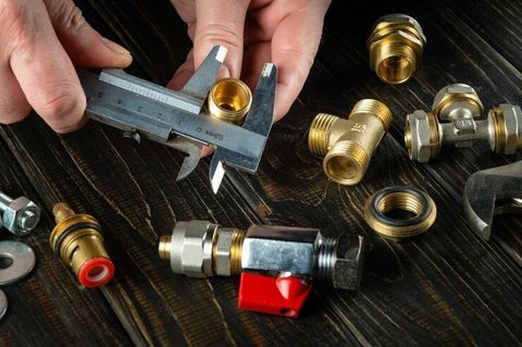
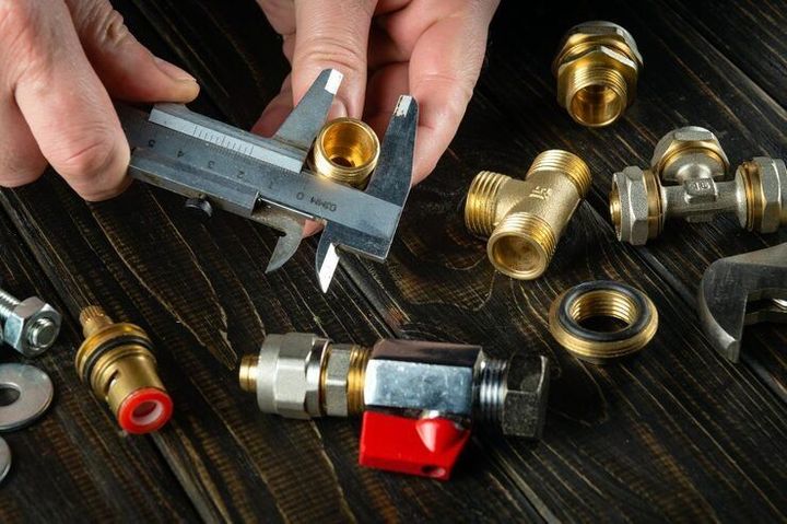
Selecting a cartridge valve involves checking its operating function, hydraulic specifications, physical dimensions, and compatibility with the surrounding equipment. Technical documentation and measurement tools help establish whether a particular design fits the intended application.
Useful Technical Resources
Several resources can support hydraulic valve research and system planning:
Manufacturer datasheets: Provide rated pressure, flow capacity, fluid compatibility, temperature ranges, and other specifications.
Hydraulic circuit diagrams: Show how pumps, actuators, valves, and other components connect and interact.
Cavity and manifold drawings: Identify mounting dimensions, port arrangements, and the cavity configuration required for installation.
ISO standards documentation: Provides information about relevant hydraulic system terminology, interfaces, and safety considerations.
Hydraulic engineering references: Explain pressure, flow, fluid behaviour, and component selection principles.
Engineering documentation should match the specific valve model and intended operating conditions.
Cartridge Valve Selection Factors
The selection process usually begins with the required hydraulic function and continues with the system's technical limits. Important factors include:
Valve function: Determine whether the circuit requires directional control, pressure regulation, flow control, or load-holding capability.
Operating pressure: Check the normal pressure and the highest expected pressure against the valve's rated limits.
Flow capacity: Confirm that the valve can handle the required fluid flow without excessive pressure drop.
Cavity compatibility: Match the valve's cavity dimensions and interface specifications to the manifold.
Fluid compatibility: Verify suitability for the hydraulic fluid and its additives.
Temperature range: Check the permitted operating temperatures for the valve, seals, and fluid.
Control method: Establish whether the application needs mechanical, hydraulic, electrical, or proportional control.
Maintenance requirements: Consider accessibility, inspection procedures, seal replacement, and contamination control.
The following table summarizes common cartridge valve types and their general functions.
| Cartridge valve type | Main function | Typical application |
|---|---|---|
| Directional valve | Changes the fluid flow path | Cylinder movement control |
| Pressure-relief valve | Limits pressure by opening a relief path | Hydraulic circuit protection |
| Pressure-reducing valve | Maintains a lower pressure in a selected circuit | Pressure-sensitive actuators |
| Flow-control valve | Regulates fluid flow | Movement speed adjustment |
| Check valve | Allows flow in one direction while restricting reverse flow | Reverse-flow prevention |
| Counterbalance valve | Controls loads that could drive an actuator unexpectedly | Controlled lowering of loads |
These categories describe general functions. Specific designs may combine several functions or use different operating mechanisms.
FAQs
What Is a Cartridge Valve in a Hydraulic System?
A cartridge valve is a removable hydraulic control component fitted into a prepared cavity in a manifold or housing. It regulates fluid direction, pressure, flow, or reverse movement according to its design.
How Does a Cartridge Valve Work?
Hydraulic pressure, a spring, or an actuator moves an internal spool or poppet. This movement changes the available fluid passages, allowing the valve to control how hydraulic fluid travels through the circuit.
What Are the Main Types of Cartridge Valves?
Common types include directional, pressure-relief, pressure-reducing, flow-control, check, and counterbalance valves. Each type performs a different function within a hydraulic system.
How Is the Correct Cartridge Valve Selected?
Selection depends on the required function, operating pressure, flow rate, cavity dimensions, hydraulic fluid, temperature range, and control method. The valve's technical datasheet and the machine's hydraulic circuit documentation provide essential information.
What Causes Cartridge Valve Problems?
Common causes include contaminated hydraulic fluid, worn seals, damaged internal components, incorrect installation, unsuitable fluid viscosity, and operation outside specified limits. Inspection and diagnosis should follow the equipment's safety procedures and technical documentation.
Conclusion
Cartridge valves regulate fluid movement, pressure, and flow in many industrial and mobile hydraulic systems. Their compact construction allows multiple hydraulic functions to be integrated into manifolds, while different valve designs address different control requirements. Recent developments emphasize electronic control, system integration, and operating-condition monitoring. Correct selection depends on the hydraulic circuit, component specifications, operating environment, and applicable safety requirements.